
I'm putting together an in-cab winch controller. The switches include a standard SPST "kill switch," which powers the DPDT momentary on-ff-on switch. the seller included the attached instructions. The independent LED circuits 7-10 are pretty obvious, but what about 1-6? my best guess is:
1 - output to winch solenoid (in)
2 - power from killswitch
3 - output to winch solenoid (out)
4 - ground
5 - ground
6 - ground
Can anyone confirm or deny?
here is a quick update in case anyone happens across this thread searching for a similar answer.
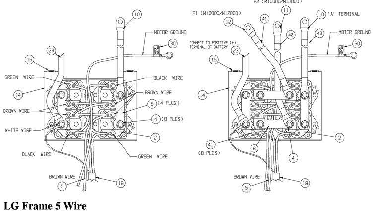
The Warn M-8000s comes factory with a contactor shown here:

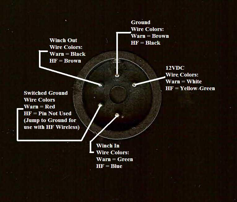
The contactor requires a switched ground as well as power. This acts as a safeguard to prevent the winch from getting stuck on if the power side shorts. shown here:

1 - output to winch solenoid (in)
2 - power from killswitch
3 - output to winch solenoid (out)
4 - ground
5 - ground
6 - ground
Can anyone confirm or deny?
here is a quick update in case anyone happens across this thread searching for a similar answer.
The Warn M-8000s comes factory with a contactor shown here:
The contactor requires a switched ground as well as power. This acts as a safeguard to prevent the winch from getting stuck on if the power side shorts. shown here: